

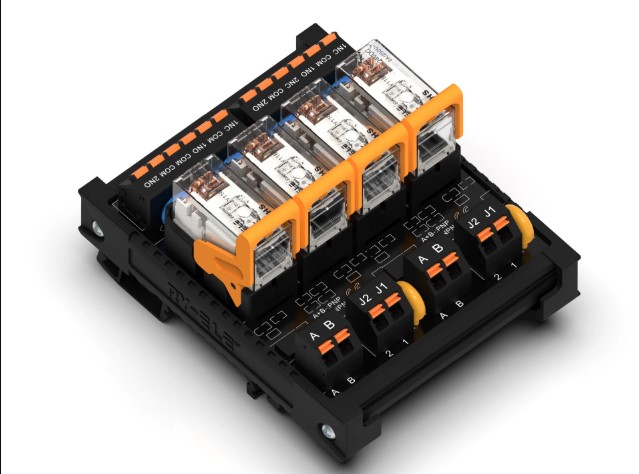
Selecting a relay socket involves more than confirming that it fits the relay physically. Electrical ratings determine whether the socket can safely handle the voltage, current, and switching conditions within the control circuit.
Before choosing a PCB mount relay socket, engineers should review its rated voltage, current capacity, insulation characteristics, and other electrical specifications. Matching these values with the relay and application helps support dependable operation and reduces the risk of premature component failure.
Check the Rated Voltage
Rated voltage indicates the maximum voltage that the socket can handle under its specified operating conditions. Engineers should compare this value with the voltage present in the switching circuit.
The socket should provide adequate voltage capacity for the intended application. Using a component outside its specified limits may affect insulation performance and overall reliability.
The relay’s coil voltage also requires attention. The socket and relay combination should suit the control circuit without creating compatibility issues.
Review the Current Rating
Current rating indicates how much electrical current the socket terminals can carry under specified conditions. This value matters when the relay controls equipment that draws substantial current.
Engineers should compare the socket’s current rating with the expected load rather than selecting a component based solely on the relay’s physical dimensions.
A suitable safety margin can also help accommodate normal operating variations and reduce excessive electrical stress on the connection.
Understand Contact Ratings
The relay’s contacts switch the connected load, so engineers need to understand the contact rating associated with the relay and socket assembly.
Important specifications may include:
- Maximum switching voltage
- Maximum switching current
- Resistive load rating
- AC or DC load capability
- Switching capacity
These values help determine whether the relay and socket combination suits the intended electrical application.
Consider Insulation Resistance
Insulation resistance describes how effectively the insulating material limits unwanted current flow between electrically separated parts.
A higher insulation resistance generally supports better electrical isolation. This specification matters in control equipment where multiple circuits operate close together on the same PCB.
Engineers should review the manufacturer’s stated insulation resistance and compare it with the requirements of the equipment.
Check Dielectric Strength
Dielectric strength, often called dielectric withstand voltage, indicates how much voltage the insulation can withstand for a specified test period without electrical breakdown.
This rating provides useful information about the socket’s insulation capability. It becomes particularly important when the relay separates control circuits from higher-voltage switching circuits.
Designers should verify the test conditions and rating in the manufacturer’s technical documentation before selecting a socket.
Look at Coil-Related Requirements
The relay coil and switching contacts serve different electrical functions. The socket needs to accommodate the relay’s terminal configuration while supporting the intended control arrangement.
Engineers should verify the relay’s coil voltage, pin configuration, and electrical characteristics. A socket that does not match these details may prevent proper relay operation.
Checking the relay datasheet alongside the socket specifications provides a more reliable way to confirm compatibility.
Consider AC and DC Applications
Electrical ratings can differ depending on whether the application uses AC or DC loads. Switching characteristics, voltage levels, and current behavior may affect the suitability of a relay and socket combination.
Engineers should therefore confirm that the socket and relay support the specific type of load used in the equipment.
This consideration proves especially useful in industrial control systems where different circuits may operate at different voltage levels.
Pay Attention to Temperature Ratings
Electrical performance can change as component temperature rises. High temperatures may affect materials, insulation, and the ability of terminals to carry current reliably.
Check the socket’s operating temperature range and consider the temperature inside the actual equipment rather than relying only on room-temperature conditions.
Applications with heat-producing components, enclosed control panels, or continuous operation deserve particular attention.
Check Creepage and Clearance
Creepage and clearance distances help maintain electrical isolation between conductive parts.
Creepage refers to the shortest path along an insulating surface, while clearance refers to the shortest distance through air. Appropriate distances help reduce the risk of unwanted electrical arcing or tracking.
The required values depend on factors such as working voltage, pollution level, insulation requirements, and applicable standards.
Compare the Socket With the Complete Circuit
Looking at one rating in isolation can lead to an unsuitable selection. Engineers should evaluate the socket alongside the relay, PCB, power supply, and connected load.
A practical review should include:
- Relay coil voltage and configuration
- Switching voltage
- Switching current
- Load type
- Insulation resistance
- Dielectric strength
- Operating temperature
- Creepage and clearance
- Applicable safety requirements
This approach helps ensure that the socket fits the complete electrical design rather than only one part of it.
Why Manufacturer Specifications Matter
Manufacturer datasheets provide the detailed electrical information required for proper component selection. Engineers should use the published specifications instead of assuming that sockets with similar appearances have identical ratings.
RY-ELE offers relay socket products for various control and automation applications. Reviewing the available specifications can help designers identify components that align with their electrical and mechanical requirements.
Final Thoughts
Electrical ratings play a central role when selecting a relay socket for PCB-based equipment. Rated voltage, current capacity, contact specifications, insulation resistance, dielectric strength, temperature range, and isolation distances all deserve attention.
RY-ELE gives engineers another source for relay socket solutions when developing control and automation equipment. Careful comparison of datasheets and application requirements can help support safe, stable, and reliable relay connections.